MOD Bus TCP
Documents >> Driver Document >>
MOD Bus TCP
The MOD Bus TCP driver will
communicate with a control device through a MODBus TCP/Ethernet
protocol.
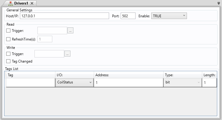
General Settings
. Host/IP: Insert the IP address of the controller
. Port: Insert the port of the controller
. Enable: Activates or deactivates the Driver Document
- True: The document will be always activated
- Condition: Activates the document whenever the condition is fulfilled
- False: The document will never activate
Read
. Trigger: If checked, will read all the inputs every time a configured tag changes its value. Select the desired tag to use as a Trigger in the TextBox beside it.
. Refresh Time(ms): If checked, will read all the inputs every specified time, in milliseconds.
Write
. Trigger: If checked, will write all the inputs every time a configured tag changes its value. Select the desired tag to use as a Trigger in the TextBox beside it.
. Tag Changed: If checked, will write an input every time its linked tag (of the Tag List) changes.
Tag List
When opening a Driver Document, it will display Driver options in the Ribbon where it is possible to create and delete Driver Items.
A Driver Item is what links a Tag from SmartView to an Input or Output of a Controller.
Once a new Driver Item is inserted, the user will have five fields to configure:

. Tag: Write the Tag that is associated with the specific address
. I/O: Select the type of input or output that going to be connected
- CoilStatus: Digital Output
- InputStatus: Digital Input
- InputRegister: Analogue Input
- HoldingRegister: Analogue Input/Output
. Address: Input the Address
. Type: Select the type of message is going to be sent
. Bit: One bit message
. Word: Sixteen bit message maximum
. DWord: thirty-two bit message maximum
. Float: Float values
. Length: Insert the length of the message to be transferred
| Holding Register | |||
| Type | Read | Write | |
| Char String | ✔ | ✔ | |
| Decimal (+/-) | ✔ | ✔ | |
| Dword 32 + | ✔ | ✔ | |
| Float 32 | ✔ | ✔ | |
| Hex | ✔ | ✔ | |
| Word 16 + | ✔ | ✔ | |
| Vector Float | ✔ | ✔ | |
| Vector Word | ✔ | ✔ | |
| Input Register | * Read Only | ||
| Type | Read | Write | |
| Char String | ✔ | ✖ | |
| Decimal (+/-) | ✔ | ✖ | |
| Dword 32 + | ✔ | ✖ | |
| Float 32 | ✔ | ✖ | |
| Hex | ✔ | ✖ | |
| Word 16 + | ✔ | ✖ | |
| Vector Float | ✔ | ✖ | |
| Vector Word | ✔ | ✖ | |
| Coil Status | |||
| Type | Read | Write | * Binary Only |
| Char String | ✔ | ✔ | |
| Decimal (+/-) | ✔ | ✔ | |
| Dword 32 + | ✔ | ✔ | |
| Float 32 | ✔ | ✔ | |
| Hex | ✔ | ✔ | |
| Word 16 + | ✔ | ✔ | |
| Vector Float | ✔ | ✔ | |
| Vector Word | ✔ | ✔ | |
| Input Status | * Read Only | ||
| Type | Read | Write | * Binary Only |
| Char String | ✔ | ✖ | |
| Decimal (+/-) | ✔ | ✖ | |
| Dword 32 + | ✔ | ✖ | |
| Float 32 | ✔ | ✖ | |
| Hex | ✔ | ✖ | |
| Word 16 + | ✔ | ✖ | |
| Vector Float | ✔ | ✖ | |
| Vector Word | ✔ | ✖ | |
Example:
01. Create CoilOutputs_Float, float in the tags document.
02. Create Modbus folder in Driver.
03. Create Driver1 document inside Modbus folder.
04. Write the Host/Ip Address and the Port.
05. Chech RefreshTime(ms) in Read
06. Chech Tag Changed in Write
07. Write CoilOutputs_Float on Tag cell
08. Select "CoilStatus" on I/O combobox
09. Write 1 on Address field
10. Run the application
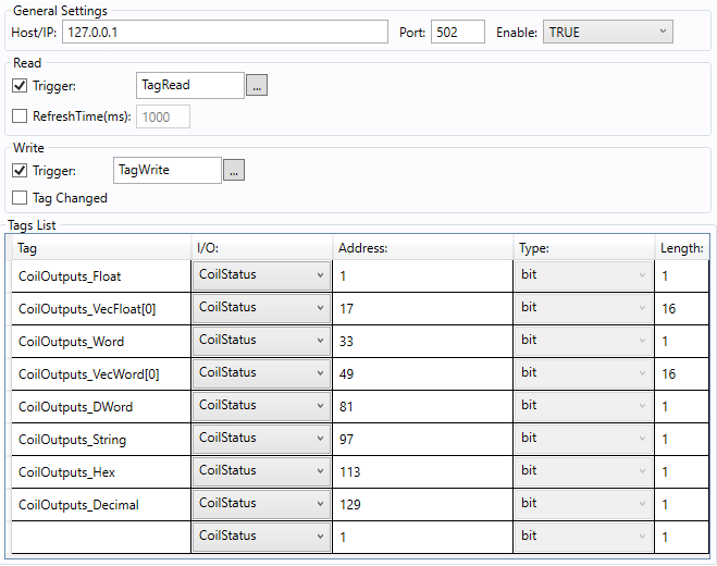
Here is an example of a configured document with Coil Status Register type:
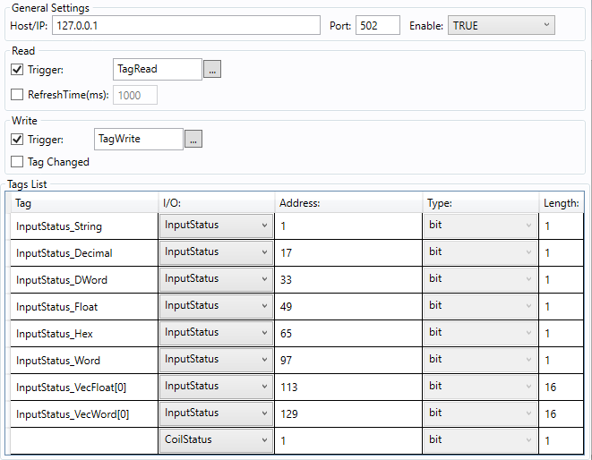
Here is an example of a configured document with Input Status Register type:
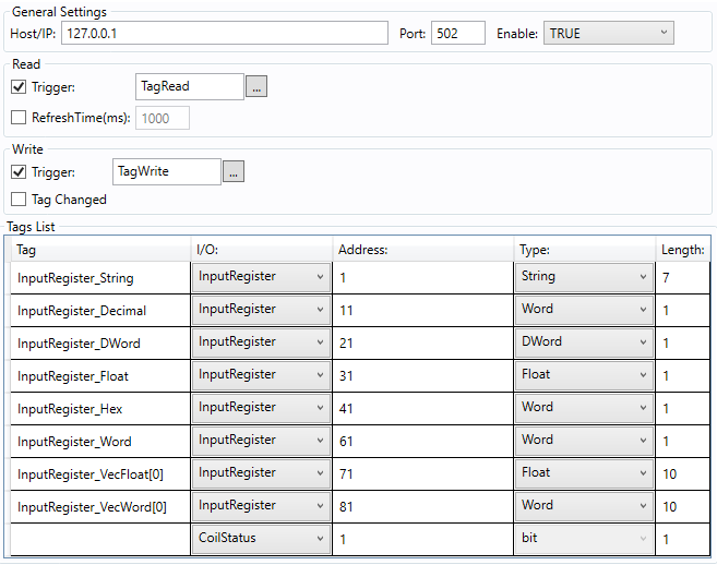
Here is an example of a configured document with Input Register type:
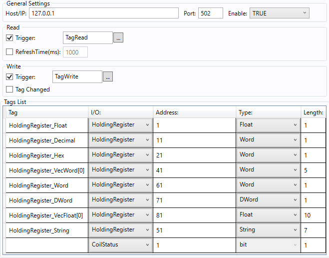
Here is an example of a configured document with Holding Register type:
|
|
|
Note: String array doesn't work, because in the ModBus driver the string is separated and every position has 2 chars, and in the Smartview a string is whole. The length field of a string item represents the number of chars that will be recovered from Modbus. |